The Hydraulic Containment feature enables the user to calculate the hydraulic gradient between pairs of wells. The hydraulic gradient is then compared against a predefined hydraulic gradient (defined by the user based on specific requirements). This feature is particularly useful for monitoring containment of groundwater flow within a specific area.
Hydraulic Containment is used in EDGE based on previous set-up of the database tables in EQuIS Professional. Once the required information is input in the database, an EDGE field EDD report is created and used subsequently in EDGE to calculate the hydraulic gradient. The steps of this work flow are presented below.
Steps in EQuIS Professional
1.RT_GROUP - The wells used to calculate the hydraulic gradient are first identified by creating a Location Group in the reference table RT_GROUP. The screen capture below shows within the RT_GROUP: the GROUP_CODE and GROUP_TYPE defined for further assessment of the hydraulic containment.

Defining Hydraulic Containment Group of Wells
2.RT_GROUP_MEMBER - In the reference table RT_GROUP_MEMBER, the Primary Well (P) is denoted by RT_GROUP_MEMBER.REPORT_ORDER = 1
Other secondary wells to compare to (S) are included in the same group, assigned with RT_GROUP_MEMBER.REPORT_ORDER >1. The actual value to compare against, for example "2-foot gradient" can be set in the RT_GROUP_MEMBER.REMARK, assuming all units are the same. If the wells are to be compared against absolute values, then RT_GROUP_MEMBER.REMARK should be equal 0.
Example: The screen capture below shows within the RT_GROUP_MEMBER, the defined GROUP_CODE, with their corresponding MEMBER_CODE, MEMBER_TYPE, REPORT_ORDER and REMARK fields. In this example, B-31 is the primary well P (denominated by REPORT_ORDER 1) while B-32 is the secondary well B-32 S used to compare against the hydraulic gradient (denominated as REPORT_ORDER 2). The actual value to compare against the hydraulic gradient is defined in the REMARK field.

Note: The Group Members need to be assigned a special RT_GROUP_MEMBER.MEMBER_TYPE e.g. "hydraulic_containment". |
3.Gradient Reversal is calculated with the logic of:
a.Assume S represents for a second location and P for a primary location compared to S.
i.When P is dry and its max of DT_WELL_SEGMENT.END_DEPTH with segment_type='SCREEN' is measured, Gradient Reversal = S's water level elevation – (P's Top of Casing - P's max end_depth) – remark, otherwise
ii.When P is dry and its measured_depth_of_well is measured, Gradient Reversal = S's water level elevation – (P's Top of Casing - P's measured_depth_of_well) – remark, otherwise
iii.Gradient Reversal = S's water level elevation – P's water level elevation – remark
Notes: •The remark is a predefined adjustment to the calculation as explained in number 2 above). •The samples of S and P locations in the equations are taken in the same day. |
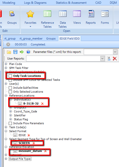
4.Create EDGE Field EDD report by selecting input parameters. The EDGE Field EDD report will subsequently be imported in EDGE.

EDGE Field EDD Report Input Parameters
5.Excel output of EDGE Field EDD
Steps in EDGE
1.Open EDGE and connect to the database.
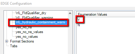
2.Ensure the enumeration for hydraulic gradients is selected from the EDGE Plugins.

Enumeration for Hydraulic Containment Option, Selected in EDGE Plugins
3.Load EDGE Field EDD file generated in EQuIS Professional.
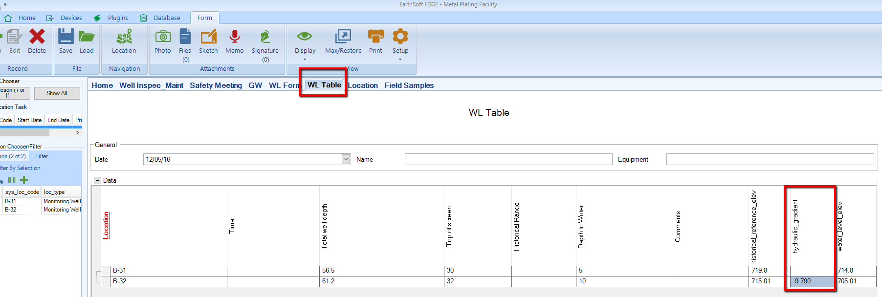
4.Select WL Table and click New.
5.The selected pair of wells will be displayed, as well as the calculated hydraulic gradient, flagging the values outside of predefined range.

